
Apr . 01, 2024 17:55 Back to list
Bottle Jack how to put a pressure gauge on a bottle jack Performance Analysis
Introduction
Bottle jacks, hydraulic lifts commonly employed for vehicle maintenance and heavy lifting operations, inherently lack integrated pressure monitoring capabilities. Adding a pressure gauge provides a critical safety and operational enhancement, allowing for precise control and verification of the applied force. This technical guide details the process of safely and accurately attaching a pressure gauge to a bottle jack, addressing the necessary components, installation procedures, material compatibility considerations, and potential failure modes. The accuracy of the pressure reading is directly tied to the selection of an appropriately rated gauge and the integrity of the connection established. Incorrect installation can lead to inaccurate readings, potentially causing operational errors and creating hazardous conditions. This guide is intended for qualified technicians and personnel experienced in hydraulic systems and safety procedures.
Material Science & Manufacturing
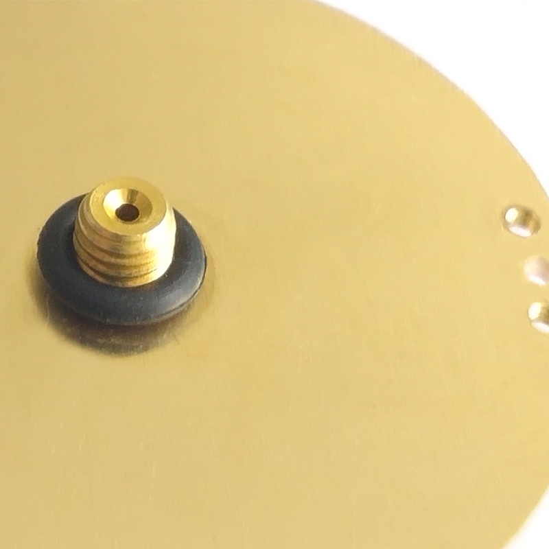
The core components involved – the bottle jack itself and the pressure gauge – are manufactured utilizing distinct material science principles. Bottle jacks typically feature a steel alloy construction, commonly AISI 1045 or equivalent, chosen for its high yield strength and ductility, essential for withstanding the substantial pressures generated during operation. The internal hydraulic fluid is typically a mineral oil-based formulation, selected for its lubricity, viscosity stability across varying temperatures, and compatibility with the jack’s seals (typically nitrile rubber – NBR). The pressure gauge's housing is frequently constructed from brass or stainless steel (304 or 316), selected for corrosion resistance and mechanical strength. The Bourdon tube, the critical sensing element, is manufactured from a specialized alloy steel, heat-treated to provide elasticity and prevent permanent deformation. Connecting fittings are often brass or stainless steel. Compatibility is paramount; the gauge’s process connection material must be compatible with the bottle jack’s hydraulic fluid and any adapter fittings used. Galvanic corrosion can occur if dissimilar metals are introduced into the system, especially in the presence of moisture. The manufacturing of the pressure gauge relies on precision machining and calibration processes to ensure accuracy, adhering to established metrological standards. Adapter fittings used to connect the gauge, often NPT or BSPT threaded, require precise thread engagement to prevent leaks and maintain pressure integrity.
Performance & Engineering
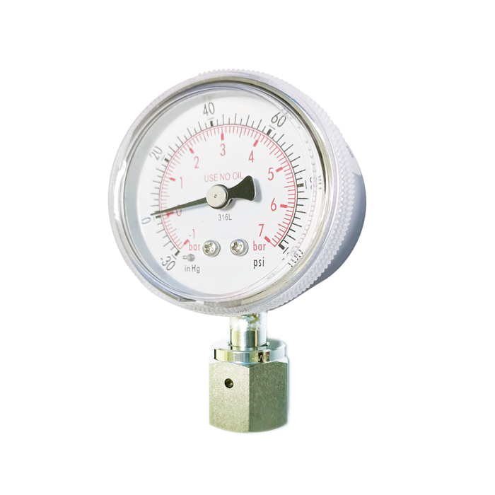
Integrating a pressure gauge into a bottle jack circuit necessitates careful consideration of hydraulic principles and force analysis. The key parameter is ensuring the gauge’s pressure range aligns with the jack’s operational capacity. Exceeding the gauge’s maximum pressure rating risks damage or catastrophic failure, while a range that is too low will provide no useful information. The pressure gauge acts as a restrictive element in the hydraulic circuit. The insertion of a gauge with a small bore fitting will introduce a pressure drop, albeit minimal if the gauge is correctly sized. Thread sealing is crucial; PTFE tape or a compatible liquid thread sealant must be applied to all threaded connections to prevent leakage under pressure. The mechanical strength of the adapter fitting is also critical. The fitting must withstand the full operating pressure of the jack without yielding or fracturing. Furthermore, the mounting location of the gauge should provide clear visibility for easy reading and be protected from physical damage. Vibration can also affect gauge accuracy; consider using a dampened mounting solution if the jack is used in a high-vibration environment. Force analysis dictates that the adapter fitting must be securely fastened to both the jack and the gauge, distributing the load evenly to prevent stress concentrations. Any potential points of weakness should be reinforced or redesigned. Regular inspection of the gauge and fittings is vital to identify any signs of wear, corrosion, or leakage.
Technical Specifications
| Parameter | Bottle Jack (Typical Range) | Pressure Gauge (Typical Range) | Adapter Fitting Material |
|---|---|---|---|
| Pressure Rating (PSI) | 2 – 50 Tons (14 - 3450 PSI) | 0 – 5000 PSI (Select based on Jack Capacity) | Brass, Stainless Steel (304/316) |
| Connection Type | Typically None (Requires Adaptation) | NPT, BSPT (1/8”, 1/4”) | Brass, Stainless Steel (304/316) |
| Accuracy | N/A | ± 1% of Full Scale | N/A |
| Operating Temperature Range | -20°C to 60°C (-4°F to 140°F) | -40°C to 85°C (-40°F to 185°F) | N/A |
| Hydraulic Fluid Compatibility | Mineral Oil Based | Compatible with Mineral Oils, Synthetic Fluids (Verify Specific Gauge) | N/A |
| Housing Material | Steel Alloy (AISI 1045) | Brass, Stainless Steel | N/A |
Failure Mode & Maintenance
Common failure modes associated with a bottle jack fitted with a pressure gauge typically stem from leakage, gauge inaccuracy, or fitting failure. Leakage can occur at threaded connections due to inadequate sealing, damaged threads, or corrosion. Internal gauge failure can result from overpressure events exceeding the gauge's capacity, causing Bourdon tube rupture or damage to the movement mechanism. Adapter fittings can fail due to fatigue cracking from repeated pressure cycling, particularly if manufactured from inferior materials or exhibiting stress concentrations. Corrosion, particularly galvanic corrosion between dissimilar metals, can weaken fittings and lead to leaks. Hydraulic fluid contamination can damage internal gauge components and seals. Maintenance should include regular visual inspection for leaks, corrosion, and physical damage to the gauge and fittings. Periodically check the gauge's calibration against a known standard. If leakage is detected, disassemble the connection, clean the threads, and reapply PTFE tape or liquid thread sealant. If the gauge consistently displays inaccurate readings, it should be replaced. The hydraulic fluid in the bottle jack should be periodically changed to prevent contamination and maintain optimal performance. Ensure that all fittings are tightened to the manufacturer's specified torque. A preventative maintenance schedule should be established based on usage frequency and operating conditions.
Industry FAQ
Q: What type of pressure gauge connection is most reliable for a bottle jack application?
A: A 1/8” NPT (National Pipe Thread) or 1/4” NPT connection, coupled with a high-quality brass or stainless steel adapter fitting, is generally considered the most reliable. NPT threads are tapered, creating a tight seal when properly tightened with PTFE tape or thread sealant. BSPT (British Standard Pipe Thread) is another option but may require a different adapter. Avoid using straight pipe threads as they are prone to leakage under pressure.
Q: How do I determine the correct pressure range for the gauge?
A: The gauge’s pressure range should be slightly above the maximum working pressure of the bottle jack. For example, if the jack has a capacity of 20 tons (approximately 2800 PSI), a 0-3000 PSI or 0-5000 PSI gauge would be appropriate. Avoid using a gauge with a range that is too high, as it will reduce accuracy in the lower pressure regions.
Q: Can I use a digital pressure gauge instead of an analog one?
A: Yes, digital pressure gauges offer increased accuracy and features like data logging. However, they typically require a power source (battery) and may be more susceptible to damage from vibration or harsh environments. Ensure the digital gauge is compatible with the hydraulic fluid and has a suitable pressure range and connection type.
Q: What precautions should I take to prevent leaks?
A: Always use PTFE tape or a compatible liquid thread sealant on all threaded connections. Tighten fittings to the manufacturer’s specified torque. Regularly inspect the connections for signs of leakage. Ensure the adapter fitting and gauge are free of any damage or debris that could compromise the seal. Verify fluid compatibility between the gauge’s internal components and the bottle jack’s hydraulic fluid.
Q: How often should I calibrate the pressure gauge?
A: The calibration frequency depends on usage and operating conditions. As a general guideline, pressure gauges should be calibrated annually, or more frequently if subjected to harsh environments or heavy use. Calibration should be performed by a qualified calibration laboratory using traceable standards.
Conclusion
The accurate integration of a pressure gauge into a bottle jack system provides a significant safety and operational advantage by enabling precise force monitoring and control. This process, however, demands meticulous attention to detail, encompassing material compatibility, proper fitting selection, adherence to torque specifications, and regular maintenance protocols. Selecting a gauge with the appropriate pressure range and a compatible connection type is paramount, alongside utilizing suitable thread sealing compounds to prevent leakage.
Ongoing vigilance through routine inspection and calibration is essential to ensure the continued accuracy and reliability of the gauge, mitigating potential hazards and maximizing the service life of the hydraulic system. Prioritizing these technical considerations will ensure a safe, efficient, and accurate lifting operation, contributing to overall operational effectiveness and minimizing the risk of equipment failure.