
Apr . 01, 2024 17:55 Back to list
Pressure Gauge how to calibrate pressure gauge Performance Analysis
Introduction
Pressure gauges are fundamental instrumentation components within numerous industrial processes, serving as critical indicators of system pressure for safety, efficiency, and process control. Calibration, the process of comparing a gauge’s readings to a known standard, is not merely a preventative maintenance task, but a necessary procedure dictated by safety regulations, quality control protocols, and the inherent drift of sensing elements over time. Incorrectly calibrated gauges can lead to inaccurate process control, potential equipment damage, safety hazards, and costly downtime. This guide provides a comprehensive, technical overview of pressure gauge calibration, encompassing material science principles, manufacturing considerations, performance characteristics, failure modes, and relevant industry standards. It targets engineers, maintenance technicians, and procurement professionals responsible for maintaining and verifying the accuracy of pressure measurement systems. The core performance of a pressure gauge, defined by its accuracy, linearity, hysteresis, and repeatability, directly correlates to the reliability of the entire system it monitors.
Material Science & Manufacturing
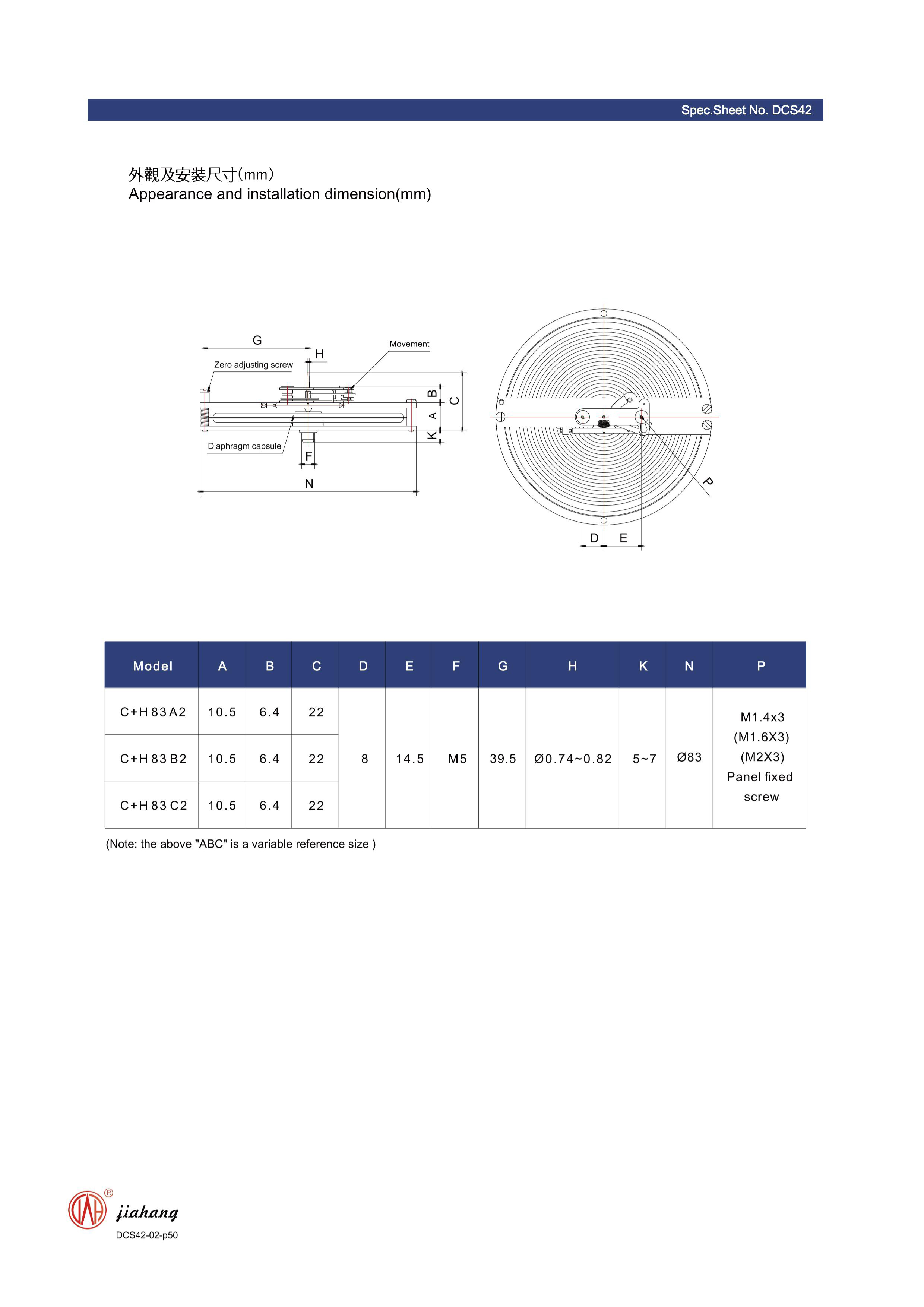
Pressure gauge construction typically involves a Bourdon tube, diaphragm, or piston element, coupled with a mechanical linkage and a dial indicator. The Bourdon tube, commonly fabricated from alloys such as beryllium copper, stainless steel (304, 316), or carbon steel, is a curved, flattened tube that straightens proportionally to the applied pressure. Material selection dictates corrosion resistance, elasticity, and suitability for the process fluid. Stainless steel offers excellent corrosion resistance but has lower elasticity than beryllium copper. Manufacturing involves precise forming, heat treatment, and welding of the tube. Heat treatment is critical to relieve internal stresses introduced during forming, ensuring dimensional stability and accurate calibration. Diaphragm gauges utilize flexible diaphragms, often made of stainless steel or Hastelloy, sealed against a calibrated spring. Piston gauges employ a precisely machined piston moving within a cylinder, translating pressure into a mechanical output. The linkage mechanism, typically constructed from hardened steel, transmits the movement of the sensing element to the dial indicator. Key parameter control during manufacturing centers on dimensional accuracy of the sensing element, surface finish to minimize friction in the linkage, and proper material heat treatment to ensure consistent elastic properties. Welding processes (TIG, laser welding) must maintain the material's integrity and prevent distortion. The dial indicator itself relies on precision gear cutting and assembly to accurately display the pressure reading.
Performance & Engineering
The performance of a pressure gauge is governed by several engineering principles. Force analysis focuses on the relationship between applied pressure, the cross-sectional area of the sensing element, and the resulting stress within the material. This stress induces deformation, which is then translated into a readable output. Environmental resistance is a crucial consideration. Temperature fluctuations can affect the material’s elasticity and cause drift in the calibration. Corrosion from process fluids can degrade the sensing element, leading to inaccuracies or failure. Vibration and shock can also introduce errors, particularly in mechanical gauges. Compliance requirements, dictated by standards like ASME B40.100, specify acceptable accuracy tolerances, safety features, and testing procedures. Functional implementation often involves incorporating gauges into larger control systems, requiring signal conditioning and data acquisition. Gauge accuracy is generally expressed as a percentage of full-scale output (FS), indicating the maximum allowable error across the entire pressure range. Linearity refers to the deviation from a straight-line relationship between input pressure and output reading. Hysteresis represents the difference in readings when approaching a given pressure from increasing versus decreasing directions. Repeatability denotes the consistency of readings under identical conditions. Proper mounting, pulsation dampening, and isolation from vibration are critical for optimal performance.
Technical Specifications
| Gauge Type | Pressure Range (PSI) | Accuracy (%FS) | Operating Temperature (°F) |
|---|---|---|---|
| Bourdon Tube | 0-300 | ±1.0 | -20 to 200 |
| Diaphragm Seal | 0-1000 | ±0.5 | -40 to 250 |
| Piston Gauge | 0-10,000 | ±0.1 | -10 to 180 |
| Digital Pressure Gauge | 0-500 | ±0.25 | -4 to 140 |
| Differential Pressure Gauge | 0-60 | ±1.5 | 0 to 150 |
| Sanitary Pressure Gauge | 0-150 | ±2.0 | -20 to 250 |
Failure Mode & Maintenance
Pressure gauge failures can stem from several sources. Fatigue cracking in the Bourdon tube or diaphragm is a common mode, particularly under cyclic pressure loading or vibration. Corrosion, especially from aggressive process fluids, can lead to pitting, erosion, and eventual rupture. Overpressure events exceeding the gauge’s rated capacity can cause permanent deformation or catastrophic failure. Hysteresis can increase over time due to wear in the linkage mechanism or plastic deformation of the sensing element. Oxidation of internal components can introduce friction and impede accurate movement. Delamination of coatings on the sensing element can expose it to corrosive environments. Regular maintenance is crucial. Visual inspection should be performed to check for physical damage, corrosion, and leaks. Periodic calibration, ideally every 6-12 months, is essential to verify accuracy. Lubrication of the linkage mechanism can reduce friction and improve performance. Replacement of the gauge should be considered if significant drift or damage is observed. Proper installation, including the use of pulsation dampeners and vibration isolators, can extend the gauge’s lifespan. Proper storage of spare gauges in a clean, dry environment is also vital to prevent degradation.
Industry FAQ
Q: What is the acceptable tolerance for a 100 PSI gauge with an accuracy class of 1.0%?
A: An accuracy class of 1.0% means the allowable error is ±1.0% of the full-scale range. Therefore, for a 100 PSI gauge, the acceptable tolerance is ±1 PSI (1.0% of 100 PSI). This means the reading can be between 99 PSI and 101 PSI when applying a known 100 PSI pressure.
Q: How often should pressure gauges be calibrated in a critical chemical processing application?
A: In critical chemical processing, where accuracy is paramount for safety and product quality, calibration should be performed more frequently. A six-month calibration interval is generally recommended. Consider more frequent calibration (e.g., quarterly) if the process involves highly corrosive fluids, significant temperature fluctuations, or vibration. Documenting each calibration event is crucial for compliance.
Q: What are the advantages of using a digital pressure gauge over a mechanical gauge?
A: Digital pressure gauges offer several advantages, including higher accuracy, improved readability, and the ability to transmit data digitally to control systems. They often incorporate features such as temperature compensation and data logging. However, they are typically more expensive and require a power source.
Q: What is the role of a diaphragm seal in pressure gauge calibration?
A: A diaphragm seal isolates the pressure gauge from the process fluid, protecting it from corrosion, clogging, or high temperatures. It is particularly useful when measuring the pressure of viscous, corrosive, or abrasive fluids. Calibration of a system with a diaphragm seal requires calibrating the entire assembly, as the seal itself introduces a degree of compliance and potential error.
Q: What impact does ambient temperature have on pressure gauge accuracy?
A: Ambient temperature fluctuations can significantly affect the accuracy of pressure gauges. Temperature changes can cause expansion or contraction of the sensing element, leading to drift in the calibration. High-quality gauges are designed to minimize this effect through temperature compensation, but it’s still a factor to consider, especially in environments with wide temperature swings. Calibration should be performed at a stable, controlled temperature.
Conclusion
Pressure gauge calibration is a multifaceted process requiring a strong understanding of material science, engineering principles, and industry standards. Maintaining accurate pressure measurement is paramount for operational safety, process efficiency, and product quality. Regular calibration, coupled with preventative maintenance practices, mitigates the risk of failure and ensures reliable performance. The selection of appropriate gauge type, based on process conditions and required accuracy, is the first critical step.
Looking ahead, advancements in digital pressure sensing technology and wireless communication will continue to enhance the capabilities of pressure monitoring systems. Predictive maintenance strategies, leveraging data analytics from calibrated gauges, will enable proactive identification of potential issues and minimize downtime. Adherence to evolving industry regulations and best practices remains crucial for ensuring the long-term reliability and safety of pressure measurement systems.