
Apr . 01, 2024 17:55 Back to list
Hydraulic Gauge Pressure Performance Analysis
Introduction
Hydraulic gauge pressure refers to the force per unit area exerted by a fluid within a hydraulic system, typically measured in Pascals (Pa), bars, or pounds per square inch (PSI). These gauges are critical components in numerous industrial applications, ranging from heavy machinery operation and aerospace control systems to precision manufacturing and automotive testing. Their function is to provide a quantifiable reading of the pressure being generated or experienced within the hydraulic circuit, enabling operators and control systems to monitor performance, diagnose faults, and maintain safe operating conditions. The accuracy, reliability, and robustness of hydraulic gauges directly impact the efficiency and safety of the overall hydraulic system. Unlike simple mechanical pressure indicators, modern hydraulic gauges often incorporate electronic transducers to provide digital outputs, remote monitoring capabilities, and increased precision. Understanding the intricacies of hydraulic gauge pressure—including its measurement principles, material construction, and potential failure modes—is paramount for engineers, technicians, and procurement professionals involved in hydraulic systems.
Material Science & Manufacturing
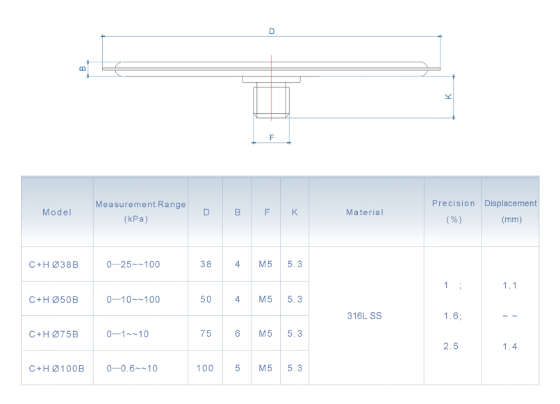
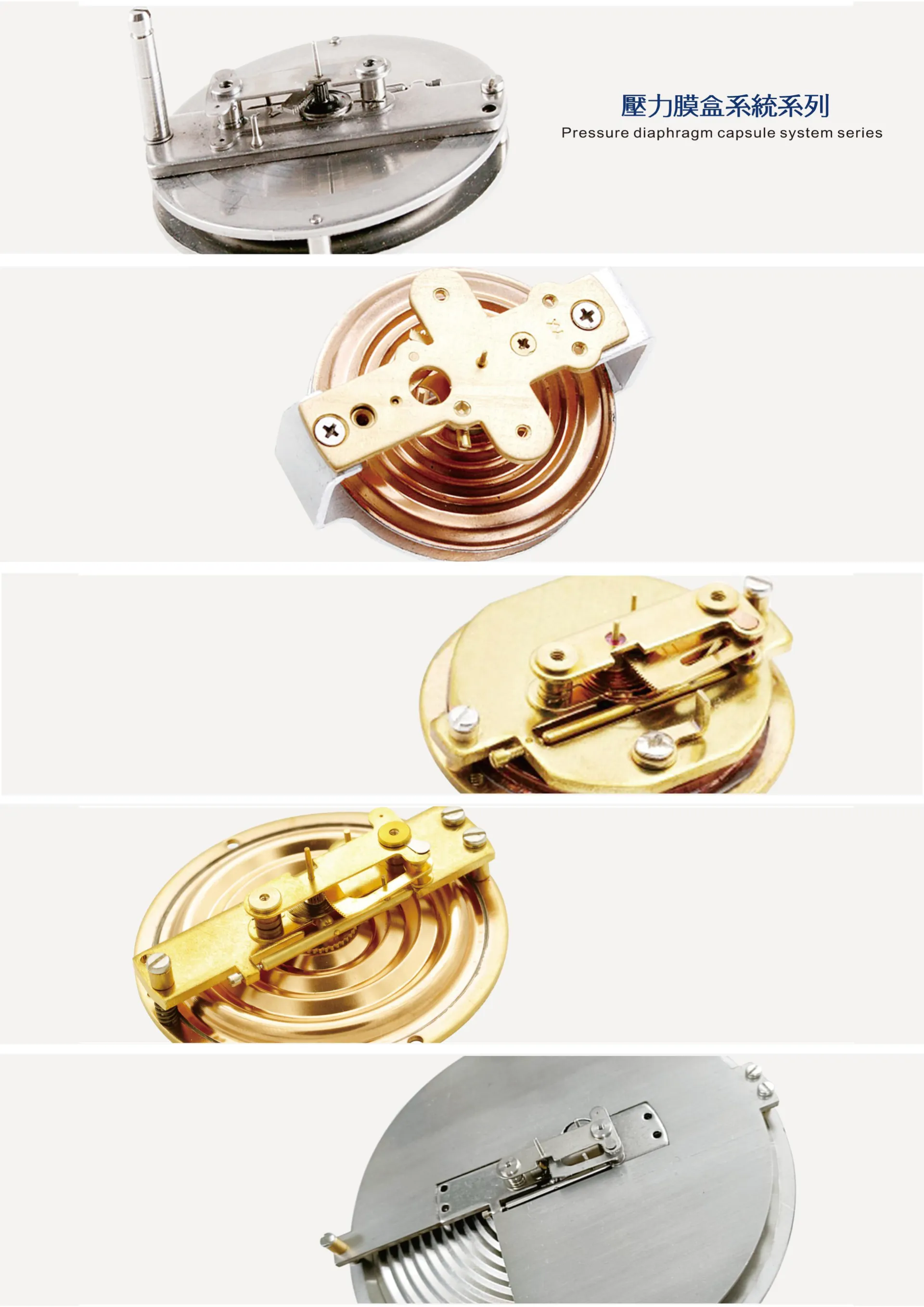
The core material for the pressure-sensing element in many hydraulic gauges is a Bourdon tube, typically constructed from beryllium copper, steel alloys (such as carbon steel or stainless steel – 304, 316), or phosphor bronze. Beryllium copper offers excellent elasticity and corrosion resistance, making it suitable for high-pressure, corrosive environments. Steel alloys provide high strength and are cost-effective for general-purpose applications. Phosphor bronze provides good corrosion resistance and fatigue life. The selection of the material impacts the gauge's accuracy and lifespan. The manufacturing process of a Bourdon tube begins with forming a flat strip of metal into a curved, elliptical cross-section. This is typically achieved through cold forming or hot bending, followed by heat treatment to relieve stresses and enhance mechanical properties. The tube is then carefully welded and sealed. The case material is often stainless steel or aluminum, chosen for durability and environmental protection. Diaphragm gauges, commonly used for lower pressure ranges, utilize diaphragms made from stainless steel or other alloys. Manufacturing of diaphragms involves deep drawing and subsequent machining for precise dimensions. Electronic pressure transducers utilize piezoresistive sensors or strain gauges bonded to a metallic substrate, typically stainless steel. The manufacturing process involves precise bonding techniques and calibration to ensure accuracy and linearity. Critical parameters controlled during manufacturing include tube wall thickness, heat treatment temperatures, welding quality, and sensor calibration. Surface finishing (e.g., passivation for stainless steel) is crucial to minimize corrosion and ensure compatibility with hydraulic fluids.
Performance & Engineering
The performance of a hydraulic gauge is fundamentally governed by the principles of stress-strain relationships within the sensing element. For Bourdon tube gauges, the deflection of the tube is directly proportional to the applied pressure, adhering to Hooke's Law within the elastic limit of the material. Engineering considerations include accounting for temperature effects, hysteresis, and linearity. Temperature variations can alter the material's elastic modulus, leading to drift in the pressure reading. Hysteresis refers to the difference in readings obtained when approaching a set pressure from increasing versus decreasing pressure directions. Linearity ensures a consistent relationship between pressure and output signal across the gauge's entire range. Diaphragm gauges rely on the deflection of the diaphragm under pressure, and engineering calculations must account for diaphragm material properties, thickness, and diameter. Strain gauge-based transducers require careful consideration of mounting techniques to minimize stress concentrations and ensure accurate strain measurement. Environmental resistance is also critical, especially in harsh industrial environments. Gauges must be designed to withstand vibration, shock, and exposure to corrosive fluids. Compliance requirements, such as those outlined by ASME B40.100 for pressure gauges, dictate accuracy classes, safety features, and testing procedures. Force analysis, including finite element analysis (FEA), is often employed to optimize the design of the sensing element and ensure structural integrity under extreme pressure conditions. Proper selection of O-rings and sealing materials is crucial to prevent leakage and maintain gauge accuracy.
Technical Specifications
| Parameter | Unit | Typical Value | Accuracy Class (ASME B40.100) |
|---|---|---|---|
| Pressure Range | PSI | 0-5000 | 1.0% of span |
| Accuracy | % of Full Scale | ±0.5% | 0.25% |
| Operating Temperature | °F | -20 to 150 | -40 to 176 (with compensation) |
| Case Material | - | Stainless Steel 304 | Painted Carbon Steel |
| Wetted Material | - | Beryllium Copper | Stainless Steel 316 |
| Connection Type | - | 1/4" NPT | 1/2" NPT |
Failure Mode & Maintenance
Common failure modes in hydraulic gauges include tube rupture (Bourdon tube gauges) due to overpressure, diaphragm failure (diaphragm gauges) due to fatigue or corrosion, and drift in calibration due to temperature fluctuations or mechanical shock. Corrosion, particularly in systems using incompatible hydraulic fluids, can lead to material degradation and eventual failure. Fatigue cracking can occur in the Bourdon tube or diaphragm due to repeated pressure cycling. Leakage at the connection points is another frequent issue, often caused by damaged O-rings or threads. Electronic transducers can fail due to sensor drift, signal noise, or component failure. Preventive maintenance is crucial to extend gauge lifespan and ensure accurate readings. Regular visual inspections should be performed to check for leaks, corrosion, and physical damage. Periodic calibration against a known pressure standard is essential to verify accuracy. The hydraulic fluid should be monitored for contamination and compatibility with the gauge materials. Gauges should be protected from excessive vibration and shock. For diaphragm gauges, ensure proper venting to avoid pressure buildup behind the diaphragm. When replacing a gauge, always use a compatible fluid and torque the connections to the manufacturer’s specifications. A thorough failure analysis, including metallurgical examination, should be conducted to determine the root cause of catastrophic failures and prevent recurrence.
Industry FAQ
Q: What is the difference between a Bourdon tube gauge and a diaphragm gauge, and when would I choose one over the other?
A: Bourdon tube gauges are generally used for higher pressure applications (typically above 75 PSI) due to their robust construction and ability to withstand significant pressure. They are relatively simple and cost-effective. Diaphragm gauges are better suited for lower pressure ranges (below 75 PSI) and are more sensitive to small pressure changes. They are often preferred in applications where accurate measurement of low pressures is critical, such as in cleanroom environments or precise control systems.
Q: How does temperature affect the accuracy of a hydraulic gauge?
A: Temperature changes can affect the material properties of the sensing element (Bourdon tube or diaphragm), leading to expansion or contraction and, consequently, drift in the pressure reading. Manufacturers often specify operating temperature ranges and may offer temperature compensation features to minimize this effect. It's important to select a gauge with a suitable temperature range for the application and to consider the potential for temperature fluctuations.
Q: What is the significance of the accuracy class specified in ASME B40.100?
A: The accuracy class defines the maximum permissible error of the gauge as a percentage of its full-scale range. A lower accuracy class number (e.g., 0.25%) indicates a more precise gauge. Selecting the appropriate accuracy class depends on the criticality of the pressure measurement for the application. Applications requiring precise control or safety-critical monitoring demand higher accuracy gauges.
Q: What types of hydraulic fluids are compatible with standard gauge materials?
A: Compatibility depends on the wetted materials of the gauge. Stainless steel is generally compatible with most hydraulic fluids, including mineral oil, synthetic fluids, and water-glycol mixtures. Beryllium copper is compatible with many fluids, but may be susceptible to corrosion in the presence of certain chemicals. It is crucial to consult the gauge manufacturer’s specifications and fluid compatibility charts to ensure proper material selection. Using an incompatible fluid can lead to corrosion, leakage, and premature failure.
Q: What are the best practices for installing a hydraulic gauge to ensure accurate readings?
A: Install the gauge in a location protected from excessive vibration, shock, and direct sunlight. Use a properly sized and sealed connection to prevent leakage. Avoid bending or kinking the connecting tubing, as this can affect the pressure reading. Ensure the gauge is mounted securely to a stable surface. When possible, use a snubber to dampen pressure pulsations and extend gauge life. Consider the effects of gravity and fluid density when interpreting the reading, especially in vertical installations.
Conclusion
Hydraulic gauge pressure measurement is a fundamental aspect of hydraulic system operation and control. The selection, installation, and maintenance of these gauges are critical for ensuring accurate readings, reliable performance, and safe operation. Understanding the underlying material science, manufacturing processes, and potential failure modes is crucial for engineers and technicians working with hydraulic systems. The appropriate gauge choice hinges on a detailed consideration of the specific application’s pressure range, environmental conditions, and required accuracy.
Ongoing advancements in sensor technology and materials science continue to drive improvements in hydraulic gauge performance, with a trend towards digital gauges offering enhanced precision, remote monitoring capabilities, and increased diagnostic features. Prioritizing regular calibration, preventive maintenance, and careful material compatibility assessment will contribute to maximizing gauge lifespan and minimizing downtime, ultimately optimizing the efficiency and reliability of hydraulic systems across diverse industrial sectors.